We are asked if we supply instructions for our many kits. In short , it is just not practical to do this as it takes an enormous amount of time and energy for little return. Most builders have some experience and there are many on line forums that are all to willing to help. However, we thought it might be useful to do a build blog of our most popular kit. So here goes.
Fuselage:
Assemble and glue the lower spine into one piece.

Bottom fuselage half is built first - no other reason than I thought this is a good place to start. Lay out the two stringers (splicing them as needed) and nominally pin them onto the plan, don't worry about the outline at this point, the formers will set the final shape. It is a good idea to split the front 150 mm of the side stringers so that they bend a bit more easily around F1 and F2.

Place all the lower formers in place, don't glue them until you are happy with the squareness and fit of the lower spline. Make sure the front former F1 is square.

Add the side stringers and the bottom 1.5 x 9.5 keel piece - as before, slit the side stringers to conform at the F1 - F2 area

This will probably take about 1.5 hours or so if using cyano. - use aliphatic to add the 1.5 x 9.5 keel strips.
Make the removable front cover - if you want to sheet it, go ahead - make sure the ends are square and the base is flat.

Attach the top formers making sure they are parallel with the lower formers - I use a couple of bits if aluminum to align them while cyanoing them in place.

Place the front cover on the model with the front flush with the F1 former.Place a piece of 1.5 mm balsa or similar between the F2D former and glue F2 in place - this will leave clearance for the cover to be removed.

On kits before 1st December 2020, make a small modification to F9A as shown

Add the rear upper formers and also the 6.5 mm sq stringer.

Add the F12 wing seats about 45mm from the front to the front of the F4 former.


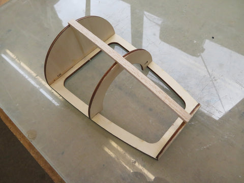
Now is probably a good time to make yourself a jig to hold the fuselage (before putting the top formers on would have been a better time!!) Cut some 18 mm or similar material to approx 150mm high x 80mm wide and then assemble the rear support with a 10mm gap between it to allow the keel to slip through. - this will allow you to sit the model on the workbench while you assemble the top formers and stringers while holding the frame flat. Pack the keel at the lowest point.

Mounting F10 showed up an error that has been there for a while - the fix to it is to cut 5 mm off the bottom of F10 (nearest the F10 part number) . (Kits after 1st December 2020 will have this modification) Make the sides of F10 flush with the 3 mm stringer and the centre 6.5 mm sq stringer - pull the rear parts together and glue.Add the 6.5 mm packers and sand flush.

Glue the 0.8mm ply to the F13 part and test fit - DO NOT glue this on until the tailplane is to be fitted and positioned.
Fin and Rudder

Glue the Rudder parts together - epoxy in the ply inserts and sand.

Assemble the Fin parts - you will need to pack these 5.0mm parts with a 5.0 mm (3/16") scrap balsa packing - the laminated F11 parts need to be packed off with a 2.5mm packer (3/32"). Once dry, shape F11 to suit the ribs.. Hinge the rudder with your favorite method.
The lower fin piece needs a small modification - add a piece of 3.0 mm balsa and sand to a wedge as shown.(Kits after 1st December 2020 will have this modification)

That's pretty much the basic fuselage done other than general shaping, nose and wing front block shaping and the strip planking of the front cover. Don't glue any of the fin and rudder on at this point.

Because I am not very good at strip planking I have tried a different way of covering the front access panel. This involves cutting a piece of very soft 3 mm balsa with the appropriate slots cut into it to form a petal. You can then completely wet the piece and tape it to the frame and let it dry. You can then glue it to the frame, preferably with superglue. Make sure the frame is pinned down onto a flat surface when you do this or it will bow badly. I covered this with two pieces. Don't worry about gluing the slots at this point.

Fill the slots from the outside with a lightweight filler so that all the joints are filled. Let dry and superglue the slots from the inside of the assembly. You can then turn it over and sand it to shape. If you want a drawing of this petal arrangement, contact us by email. (or I will figure out how to add it to this blog!)


Laminate the nose block from the 3.0 mm and 8.0 mm sheets (this was not supplied in kits before August 2020) and then shape to suit .
Tailplane:

release the tailplane parts from the appropriate sheets. Glue the 1.5 mm ply brace to the centre of the tailplane rear spar/trailing edge, making sure it is centered.

Note that the tailplane and elevators need to be packed up by approximately 3.0 mm in order for the 6.5mm sq leading edge to clear the bench (You could overhang the leading edge over the edge of the building bench and build the rest of it flat on the building board).
Trial pin the tailplane and elevator assemblies together sanding the joints square where required, make sure you set it up with a 1.5 mm spacer between the hinge line. Make sure S5 ( the centre pieces of the tailplane) are flush with the bottom of the tailplane - these will be the main contact point for gluing the tailplane to the fuselage.
Once you are happy with the fit and shape, glue the assembly together and leave to dry thoroughly.

Just before removing it from the building board, saw through the end to release the elevator.

Remove from the building board and sand and shape tailplane and elevators to suit. You will need to razor plane the trailing edge on the elevators to maintain an airfoil shape. Mark the hinge line (3.0 mm from the bottom of the tailplane and hinge with your favorite method - you will need to cut a fine slot in the ply doubler to accommodate the inner hinges. It took me a little longer that I would have thought for this - about 3 hours from start to finish with cyanoacrylate glue.
The Wing Assembly
There is a lot of preparation required to build each wing - this entails laminating the trailing edges and wingtips - make sure you assemble the rear trailing edge as shown.

Use a good aliphatic or a similar type wood glue - allow to dry thoroughly overnight.

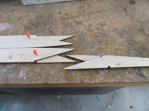
If you have a recent kit, the spars and leading edge need joining - sand or cut a shallow angel in each half and glue with a good quality aliphatic - clamp them to a straight edge or to a bench ensuring they are straight and the joint is compressed.

Definitely leave these to dry thoroughly for at least 24 hours.

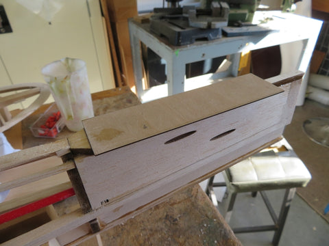
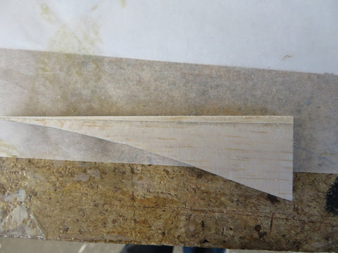
Taper the end of the 12.5 x 6.5 Main Spar as shown (215 mm x 5 mm ).

Pin all the trailing edges in place - I have added a lot of packing spacers to the drawing - if you want a copy of this, please email me and I will send you a pdf of the thickness of the spacers. At this time it is important to use the supplied jigs to set the dihedral angle of the centre rib with the supplied jigs. Pin everything together to make sure you are happy with the position and fit.
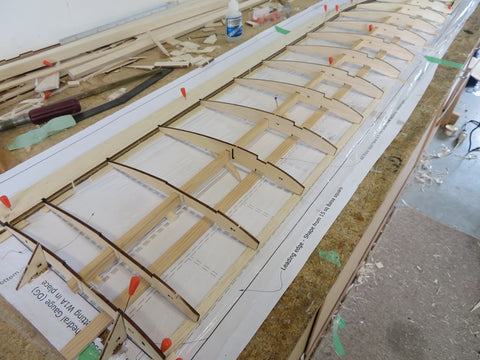

Note that the centre spar is packed up using a 6.5 mm sq packer.
Make sure you put the lower 12.5mm x 3.0mm sub spar under the wing ribs so that it can be lifted up into place in the next step (I have a short bench!)
Once you are happy with everything, glue the main spar and trailing edge to the ribs - I used cyano as it is more than adequate for this.

Lift up the lower sub spar and glue in place - make the shear webbing from 6.5mm balsa - cut this to exactly 14.0 mm and glue it in place.


Add the Top Sub spar and the leading edge - I chamfered the edge of this to make it fit. 
Add in the sub ribs, you may have to sand the back face , depending on where the 6.5 mm shear webs where placed.

Add the top of the Dihedral brace box.

Cut out the parts of the ribs that accommodate the wing spar.

Fit the spar side plates and glue with epoxy, make sure there is no excess glue oozing out into the area where the spar goes. Place the spar in the slot (above any potential glue) while it goes off. Once dry, glue in the bottom ply piece taking care to keep any excess glue out of the slot.

Add a spare sub rib at the point where you want to join the sheeting - its at the W2 rib.


Shape the leading edges with a good modelling plane and apply the sheeting, pinning it and taping it down. The top of the wing first and then to the bottom. This should be done in steps, top first, with it being pinned down and let to dry, then trim off excess and turn it over and do the bottom side, again with it pinned down.
There is a small addition you need to add to the bottom of W4 - its about a 3mm wedge as shown below.
Once all is dry, shape the leading edge and trailing edges and do a final sand of the balsa - this is essentially the process for the wing build - Repeat for the second side.
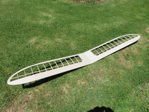
The finished item.
Now is the time to glue on the tailplane support, get it set up and place a flat heavy-ish item on it to measure the distance from the base datum to ensure it is level - epoxy in place.